Current Non-SCA Collimators' Problems
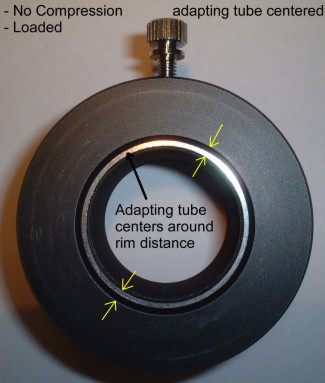
1. The Thumbscrew Gap:
The thumbscrew pushes the laser collimator off to one side of the adapting eyepiece focuser. This off-axis distance creates a gap between the collimator's outside diameter and the focuser’s inside diameter. No matter how accurately the laser is internally aligned, the displacement gap offsets the laser when fastened with the thumbscrew.The displacement may seem small, but the misalignment grows when the laser beam travels a relatively short distance. With slightly off, miscollimated mirrors in a fast telescope (F/5 or faster), the problem compounds substantially. The illustrations below show how the laser beam is offset in three scenarios when the laser travels from the collimator to the primary mirror (in red line) and returns to the laser origin (in blue line).
In figure 1, the primary and the secondary mirrors are collimated but the laser is installed offset, by the thumbscrew, from the true optical axis. The laser only travels roughly parallel along the optical axis, but not on the axis, and returns with the same initial offset distance (assuming the focuser tube is parallel to the optical axis).In this case, the user will be tricked into adjusting the secondary mirror first to center the laser dot on the primary, then adjusting the primary to point the laser back to the center of the true optical axis.The attempt ruins a perfectly collimated telescope by adding astigmatism from the tilt compensation.
collimated misaligned
In figure 2, the primary is off 1 degree and the secondary is square to the focuser, and again the laser is installed offset from the true optical axis cause by the thumbscrew.The deviation of the returning laser dot from the primary increases compared with the figure 1 scenario.
In figure 3, the primary is collimated, the secondary is off 1 degree to the true optical path, and the laser is installed offset from the true optical axis caused by the thumbscrew.The deviation of the returning laser dot from the primary increases more.
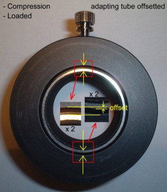
2. Adapting with Unified Compression Ring
The unified compression ring does not do what it states.The mechanism simply uses a thumbscrew crushing (but not uniformly contracting) an internal brass ring to clamp on the inserted tube.When you take a closer look, it only forces the brass ring to bend into an off-centered oval ring creating two clamping points (not 360 degrees surface contact as you thought would be) on the inserted eyepiece tube (see photos below).
 
This spells disaster for a laser collimator.
With two sides clamping down creating two linear contacts, the compressed ring opens the other two sides wider even with a relief cut in the ring.
B
y design, the brass ring has to be larger than the adapting tube, so the total widened gap is even wider than the simple thumbscrew method.
The two-point clamping allows the inserted tube to wiggle/pivot on the wide/tangent sides. The only thing preventing it from pivoting is making sure the shoulder of the laser collimator is flush against the rim of the focuser and is tightly locked down with the compression ring.
But when you wiggle the laser collimator just a little more, you will find it starts to loosen up which allows the laser to dance around on the projecting mirrors in the orthogonal directions of the clamping points.
This “dancing laser spot” problem gets real frustrating
because the
user cannot repeat the laser collimation consistently.
|