|
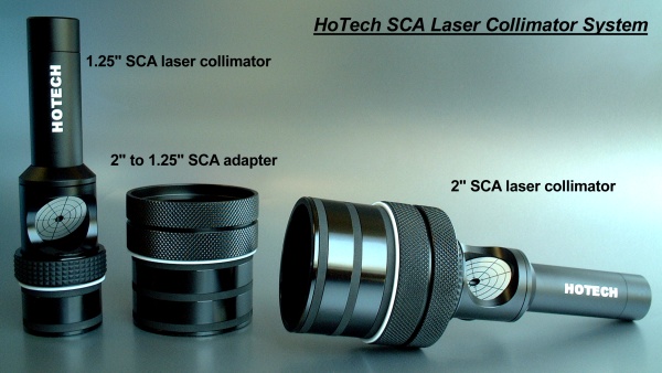
HOTECH SCA Laser Collimator Patented
Innovations in simple and precision form for maximum accuracy
 .gif)
1. Why we should NOT test the laser alignment by putting the laser on a v-block.
It is a very common method to check for laser alignment which someone ever suggested in the internet. When you take an extra step to think about, this method is referencing two center points at which one of them is irrelevant because one is on the none-adapting section, namely the body section of the device.
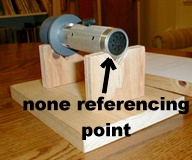
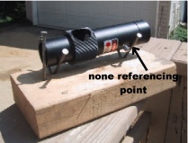
The front 1.25" or 2" collimator adapting section should be the only place to be rotated about on the v-block. Therefore the two contacting points should be within the distance of the adapting section. It is difficult to test with the referencing points are very close to each other in which the clamping jig requires some desgin to accomplish. This v-block technique only works with uni-body construction laser collimator at which the entire body from the adapting section to the end of the body is machined from one piece of material.
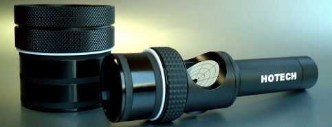
Our SCA Laser Collimator is constructed in three sections (the SCA adapter, the viewer, and the battery compartment). These sections are well machined and carefully assembled, but the mechanical error from the SCA adapter to the end of the battery compartment does not represents the true pointing axis if placed on the v-block like the suggested photos below.
The most effective way to check for the pointing error is insert the laser in the focuser with slightly tighen resistant on the SCA adapter, and rotate the the laser collimator by keeping it flush against the focuser shoulder. Then you check the rotating laser dot on the primary mirror for pointing error.
2. Should we collimate with where the eyepiece is, which is not centered.
You want at least your mirrors in your Optical Tube Assembly(OTA) are square so you have one less problem to worry. You cannot fix the out-of-alignment-car by just balancing the tires. These are separate issues.
We have seen numerous optical lens polishing machines in production. The concentricity of each manufactured lens varies even made from the same machine because each lens is cut slightly different from the raw material, is glued slightly different on the polishing jig, and is polished slightly different at the initial polishing angle in reference to its edge. These small differences just add up to some level of errors. So the lens is usually designed to have larger sweet zone to compensate the errors. Therefore the true optical center for an eyepiece lens is more forgiving than the laser due to its larger sweet zone. A small thumbscrew offset installment is tolerable to certain extent (not for high power eyepiece). And this is where the X-Y Positioner comes in handy. It can actually compensate the optical errors of each eyepiece by shifting the x/y position of the eyepiece at the focal point to find the sweet zone on each eyepiece.
In contrast, the laser is extremely sensitive to its installation. A slight offset installation will cause the laser to shift from the true optical axis. And for some poorly made unified compression ring, the losse tolerances between the compression brass ring, ring groove in the focuser, and the uneven tip of the locking thumbscrew will create different angular pivot depending on how hard the user locks the thumbscrew. Try to put a standard laser collimator in the focuser and watch how the projecting laser dot on the primary mirror moves with different locking tightness from the thumbscrew. The focuser slop really plays a big part in the pointing errors of a laser collimator. See this videofor the locking error demonstration.
Moreover, the focuser ID has to be larger to accept the eyepiece or laser, and then the gap became a slop problem. Every focuser, eyepiece and laser has tolerances. The gap between the focuser and the accepting device will just add up differently from eyepiece to eyepiece even on the same focuser. Therefore, the optical axis shift to one side of the focuser tube locks in by the thumbscrew varies from each inserting item. Some people assume the optical axis offset by thumbscrew is consistent with eyepiece and any none SCA laser collimator. But in fact, they are not constant.
Locking the laser with the thumbscrew may not represent the same optical axis from all the eyepieces you use in the same focuser tube. The distance is small, but it is real.
SCA collimator keeps the collimation in the closest approximation with various adapting eyepieces in the focuser. And the SCA Technology can help to keep the laser in place without using the thumbscrew.
3. How to Install and remove the SCA Laser Collimator from your telescope.
The SCA is a new technology. It requires some understnading of the simple steps to master the technique for a lasting accurate installation. Please view the video link for your reference. http://www.youtube.com/HoTechUSA
4. How to collimate the Newtonian/Dob telescope using SCA Laser Collimator.
Please view the video link for your reference. http://www.youtube.com/HoTechUSA
5. How to collimate the SCT using SCA Laser Collimator.
Please view the videos in the following sequence for an accurate procedure:
1. SCT Collimation-1-Intro
2. SCT Collimation 2-Laser Setup
3. SCT Collimation-3-Laser Collimation
Here is the link. http://www.youtube.com/HoTechUSA
6. How to collimate the Newtonian/Dob telescope using Barlowed technique.
We will be releasing the video in the near future for your reference.
7. Is Barlowed Laser Collimation Effective?
Yes, you can barlow our SCA Laser Collimator for your primary mirror collimation by placing it in a barlow lens OTA and align the combination accordingly. In addition, the SCA technology improves the accuracy of the barlowed laser system by keeping the laser coincident with the optical center of the barlow lens in the OTA, and making the assembly even more accurate. Conventional thumbscrew on the barlowed lens OTA will not center load the installed laser.
The technique is brilliant and is proven that a barlowed Laser makes the laser pointing error less sensitive. The technique relaxes the positioning and pointing error of an installed laser in the system, and it also relaxes the positioning and pointing error of the entire system in the focuser. It combines the ease and convenience of a laser collimator with the accuracy of the Cheshire and you can perform the collimation in the dark.
However, barlowed laser technique solves half of the collimation problem becasue it only collimates the primary mirror. You will still need the help of the quick and easy to use SCA Laser Collimator to collimate the secondary mirror. And of course, always use star collimation as your final collimation.
8. Diffraction Grating Technique with SCA Laser Collimator
Since our SCA Laser Collimator is already accurate with the SCA technology, fine laser dot, and the built-in 45 degrees faceplate, there is no need to use the DFG pattern to align the primary mirror of a Newtonian telescope. The purpose of using DFG pattern is to gross alignment the primary mirror. The user aligns the primary mirror by referencing the shadow of the secondary in the projected DFG pattern on a wall, and user counts the DFG dots around the shadow to center in the shadow. This method cannot achieve accurate alignment because the gap between each dot can make a big alignment difference. At the final alignment stage, the user must bring the laser dot back to the laser exit (the center of the 45 degrees faceplate). Our built-in 45 degrees faceplate allows you to align your primary mirror from the rear of the telescope eliminating traveling to the front of your scope repeatedly during collimation like other collimators. Therefore, there is no need to use DFG lens in conjunction with our SCA Laser Collimator.
|